4-inch IPS touch display · Raspberry Pi
HyperTouch 4.0
High-resolution IPS display with capacitive multi-touch for the Raspberry Pi. The picture comes over the DPI interface straight from the 40-pin header, with no HDMI cable and at 60 frames per second. It fits every Raspberry Pi with a 40-pin header, and a Pi Zero can also be soldered on directly.
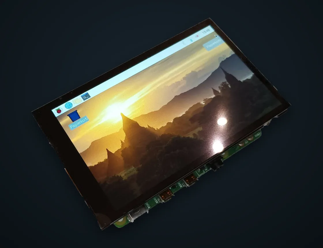
- 800 × 480
- IPS, 350 cd/m², viewing angle up to 160°
- DPI · 60 fps
- 18-bit RGB straight from the 40-pin header
- Multi-touch
- capacitive, GT911 compatible, via I²C
- 32 steps
- backlight with single-wire dimming
Mounting
The display plugs onto the Raspberry Pi with the supplied 40-pin header extension. No soldering is needed. Alternatively, a Pi Zero can be soldered flat onto the adapter board to save space.
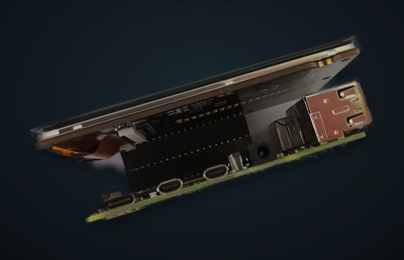
- Spacing20 to 27 mmBoard to board, freely adjustable. The header extension must sit at least 3 mm deep in the display socket, but not all the way.
- CoolingAt least 5 mm above the USB sockets5 to 12 mm depending on insertion depth. This leaves airflow for a Pi 4 and room for a case or CPU cooler.
- ScrewsMirrored Pi mounting holesThe adapter board has the Raspberry Pi mounting holes. With M2.5 standoffs (e.g. Würth Elektronik 970200154) everything can be screwed together.
Plugging on
- Insert the header extension into the display first, not into the Raspberry Pi. It is deliberately very tight so it stays stable at large spacings, and it is hard to remove afterwards.
- Newer revision: before gluing. If the display is not yet glued to the adapter board, insert the header first. If it is already glued, do not press on the display near the display cable while inserting.
- Plug onto the Raspberry Pi and set the spacing you need.
- Screw down if needed through the mirrored mounting holes.
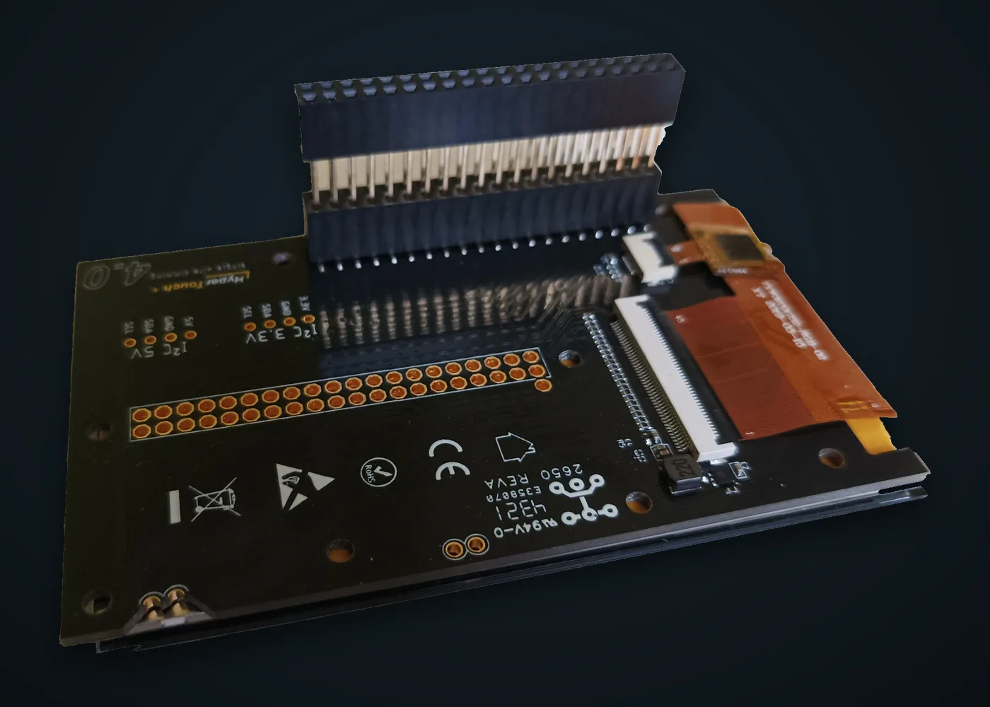
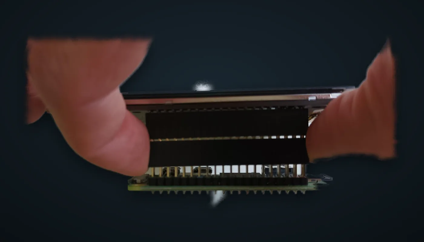
Leave the header in the display
Do not pull the extension out of the display again, or individual gold spring pins may come loose. With variable-height extensions this cannot be avoided by design. Loose pins can be carefully pushed back into the plastic part.
Remove by the header
When taking the display off the Raspberry Pi, do not apply force to the display. Hold the header extension and pull the display off together with it.
Soldering a Pi Zero (advanced)
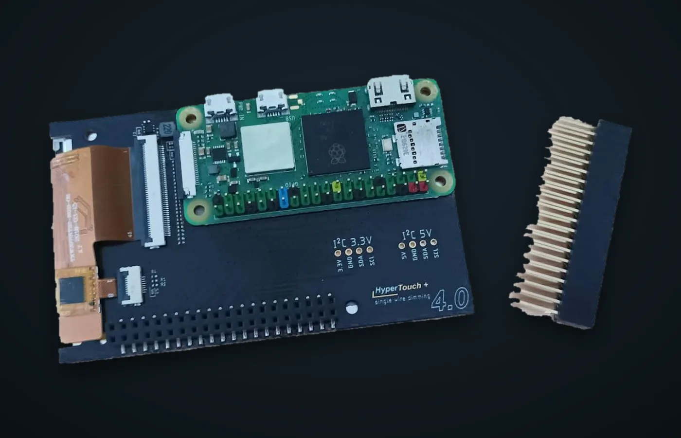
Pi Zero models can be soldered flat onto the adapter board, with or without a pin header. Soldering is done from the back. To do this, carefully detach the display from the board; it is held by double-sided tape.
Without a pin header, align and fix the Zero through the holes first, for example with a match.
Only with this mounting are the I²C 5V pads usable, see Pinout.
Installation
Drivers and device tree overlays are on GitHub at shpi/hypertouch40. The installer builds the kernel module for backlight and display initialisation with DKMS, adds the overlays to config.txt and asks for driver mode and rotation. Run it on the Raspberry Pi, over SSH or on an HDMI monitor.
curl https://raw.githubusercontent.com/shpi/hypertouch40/main/get-hypertouch.sh | sudo bash
- Install Raspberry Pi OS (32 or 64 bit) and boot the Pi with a network connection.
- Run the command above. It installs Git, clones the repository to
/usr/src/hypertouch40and startsinstall.sh. - Choose the driver mode:
1KMS/DRM, recommended for current systems (still beta on the Pi 5), or2Legacy with framebuffer. - Choose the rotation, see table.
- Reboot.
| Option | Rotation | Orientation |
|---|---|---|
| 1 | 0° | Portrait, header on the right (default) |
| 2 | 90° | Landscape, header at the bottom |
| 3 | 180° | Portrait, header on the left |
| 4 | 270° | Landscape, header at the top |
Manually
Without the one-liner: clone the repository and start the installer directly.
git clone https://github.com/shpi/hypertouch40.git
cd hypertouch40
sudo ./install.sh
32 or 64 bit, but not mixed
Raspberry Pi OS with 32 bit (armhf) and with 64 bit (arm64) are supported. A 32-bit system with a 64-bit kernel or vice versa is detected and the installer stops, because DKMS cannot build a module for it. To stay on a 32-bit system, set arm_64bit=0 in config.txt and reboot.
Updating an older installation
Simply run install.sh again. It removes obsolete entries such as dtparam=addr= and gpio=27=pu or gpio=27=pd by itself. There is no touch address to choose anymore.
Uninstall
Removes the kernel module, the overlays, all HyperTouch entries in config.txt (backup as config.txt.bak) and the rotation helpers. Reboot afterwards.
sudo /usr/src/hypertouch40/install.sh --uninstall
Brightness and rotation
Brightness
The backlight is driven by a Diodes AL3050, dimmed over a single line (GPIO 19). The driver exposes it as a Linux backlight with levels 0 to 31.
echo 31 | sudo tee /sys/class/backlight/soc:backlight/brightness
If the path soc:backlight does not exist, ls /sys/class/backlight/ shows the correct name.
Rotation
Changing the rotation
Run the installer again and choose a different rotation. Picture and touch are set up to match each other.
KMS
The touch stays in its base orientation. The installer writes a Wayfire mapping for the DPI-1 output and adds an autostart helper that uses wlr-randr or xrandr in other sessions.
Legacy
The installer sets display_lcd_rotate= and the matching touchscreen axes in config.txt.
Troubleshooting
Touch does not respond
The number of the software I²C bus can differ between systems. List the buses first, then scan the bus named i2c-ht40:
i2cdetect -l
i2cdetect -y <bus-number>
The touch controller shows up as UU (claimed by the driver) at 0x14 or 0x5d.
Two possible touch addresses
The GT911 latches its address from the level on GPIO 27 at power-on. Its reset is hardwired to 3.3 V, so software cannot restart it. The address can even change between a cold boot and a reboot. The overlays therefore declare both addresses and the kernel binds to the one that answers.
Harmless messages
For the other address, dmesg shows a short error block, for example Goodix-TS 22-005d: I2C communication failure: -6. The line Goodix-TS 22-0014: ID 911, … then confirms the touch works. Repeated vc4-drm gpu: bound … lines at boot are normal too.
“Pin already requested”
DPI needs almost all GPIOs. The installer therefore disables dtparam=i2c_arm=on (pins 2 and 3) and enable_uart=1 (pins 14 and 15). If they are switched on again, display or touch may fail.
Kernel header or DKMS errors
Usually system and running kernel do not match (mixed 32/64 bit). Use a matching image, or on a 32-bit system set arm_64bit=0, reboot and run the installer again.
Help
If nothing helps, write to lh@shpi.de, ideally with the Raspberry Pi model, the Raspberry Pi OS version and the output of dmesg.
Pinout
The display uses almost the entire 40-pin header. The picture runs in parallel over 18 data lines and four control lines (DPI), the touch over a software I²C bus on GPIO 10 and 11.
| Function | GPIO | Pin | Pin | GPIO | Function |
|---|---|---|---|---|---|
| 3.3 V | – | 1 | 2 | – | 5 V |
| DPI V-sync | 2 | 3 | 4 | – | 5 V |
| DPI H-sync | 3 | 5 | 6 | – | GND |
| DPI blue 2 | 4 | 7 | 8 | 14 | DPI green 4 |
| GND | – | 9 | 10 | 15 | DPI green 5 |
| DPI green 7 | 17 | 11 | 12 | 18 | Display chip select |
| Touch interrupt | 27 | 13 | 14 | – | GND |
| DPI red 4 | 22 | 15 | 16 | 23 | DPI red 5 |
| 3.3 V | – | 17 | 18 | 24 | DPI red 6 |
| I²C SDA (touch) | 10 | 19 | 20 | – | GND |
| DPI blue 7 | 9 | 21 | 22 | 25 | DPI red 7 |
| I²C SCL (touch) | 11 | 23 | 24 | 8 | DPI blue 6 |
| GND | – | 25 | 26 | 7 | DPI blue 5 |
| DPI pixel clock | 0 | 27 | 28 | 1 | DPI data enable |
| DPI blue 3 | 5 | 29 | 30 | – | GND |
| DPI blue 4 | 6 | 31 | 32 | 12 | DPI green 2 |
| DPI green 3 | 13 | 33 | 34 | – | GND |
| Backlight | 19 | 35 | 36 | 16 | DPI green 6 |
| Display data (SPI) | 26 | 37 | 38 | 20 | DPI red 2 |
| GND | – | 39 | 40 | 21 | DPI red 3 |
Picture data (DPI)Control, touch, backlightPowerGround
GPIO 18, 26 and 27 initialise the display controller at boot (chip select, data, clock). After that, GPIO 27 is the touch controller interrupt. That is why the installer always loads the hypertouch40 module before the Goodix touch driver.
I²C pads
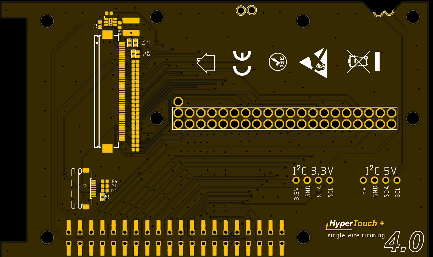
- I²C 3.3V3.3 V · GND · SDA · SCLConnected to the software I²C bus of the touch controller (GPIO 10 and 11, pull-ups on the board). Further I²C devices can be connected here as long as their addresses are not 0x14 or 0x5d.
- I²C 5V5 V · GND · SDA · SCLOnly usable with a soldered-on Pi Zero.
- Holes2.54 mm pitchFor a pin header or directly soldered wires.
Schematic
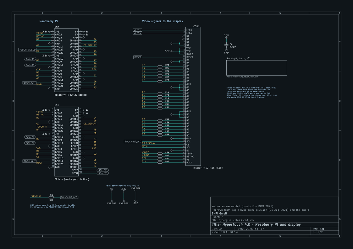
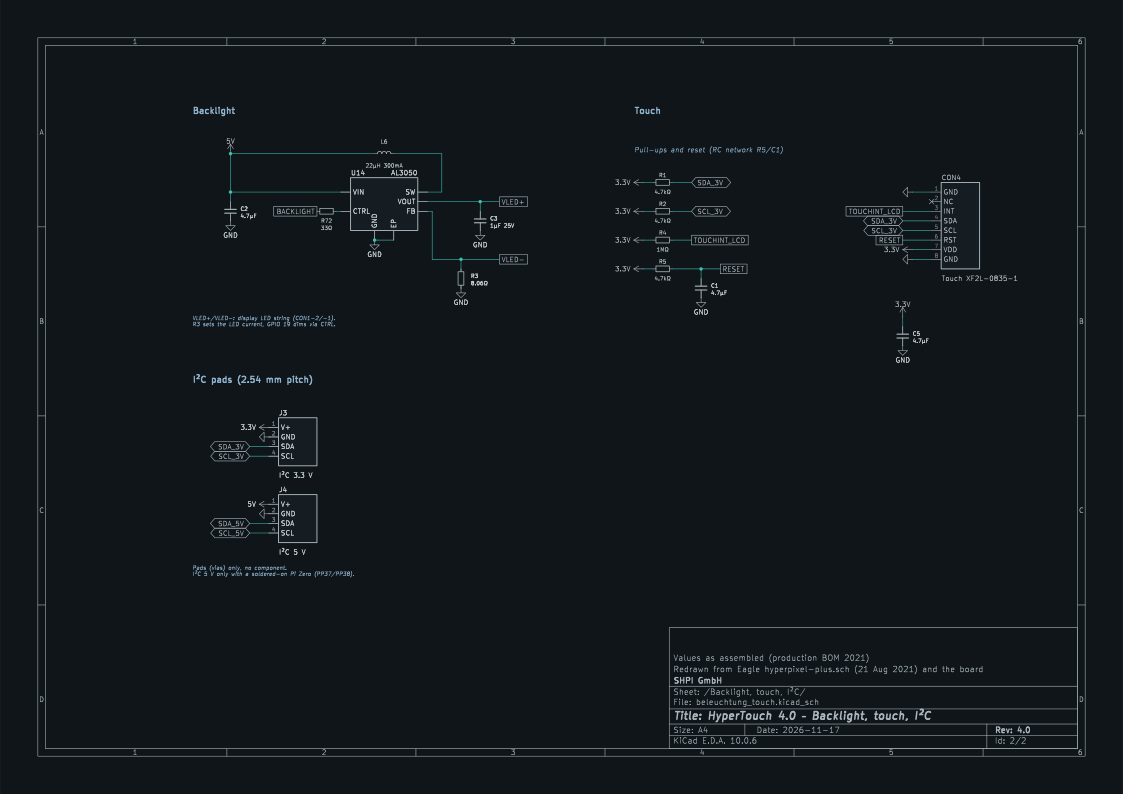
The schematic has been redrawn in KiCad on two A4 pages. It is based on the 2021 Eagle schematic and the board: all connections are checked against the board and the values match the production BOM. Click a page to open it full size.
PDF, 2 pages A4Page 1 (SVG)Page 2 (SVG)
Video signals
18 colour lines (R2–R7, G2–G7, B2–B7), pixel clock, data enable, H-sync and V-sync run from the Pi header through one 33 Ω series resistor each to the 45-pin display connector CON1 (Hirose FH12-45S-0.5SH, 0.5 mm pitch). The resistors damp reflections on the fast lines.
Display connector
The CON1 pin names follow the panel datasheet (TXW397017S4-AS). The Pi's 6 bits per colour go to panel pins R5–R0, G5–G0 and B5–B0; bits 7 and 6 of each colour are tied to GND.
Display initialisation
The ILI9806E display controller is configured over SPI at boot: chip select on GPIO 18 (CS_DISPLAY), data on GPIO 26 (MOSI), clock on GPIO 27. Display and touch controller share their reset via the RC network R5/C1 (4.7 kΩ, 4.7 µF) to 3.3 V.
Backlight
U14 (Diodes AL3050) is a boost converter for the display's LED string. It runs from 5 V with inductor L6 (22 µH) and supplies VLED+ to CON1-2. The LED current flows through VLED− (CON1-1) and R3 (8 Ω) to ground; R3 sets it via the FB input. GPIO 19 dims it through R72 (33 Ω) on the CTRL input.
Touch
The touch controller connects to the 8-pin connector CON4 (Omron XF2L-0835-1). SDA and SCL (GPIO 10 and 11) have 4.7 kΩ pull-ups (R1, R2), the interrupt on GPIO 27 a 1 MΩ pull-up (R4). It is powered from 3.3 V, buffered by C5.
Pi Zero and R43
The Pi Zero solder pads U$1 are connected in parallel to the socket U$2. Only pin 13 goes through R43 to the touch interrupt there; the socket connects directly. The old Eagle schematic still listed 604 Ω for the series resistors and 30 Ω for R72; 33 Ω are fitted.
Bill of materials
Parts as assembled, according to the 2021 production BOM.
| Ref | Qty | Value | Purpose | Part | LCSC |
|---|---|---|---|---|---|
| U14 | 1 | – | LED driver, boost converter | Diodes AL3050FDC-7, U-DFN2020-6 | – |
| L6 | 1 | 22 µH, 300 mA | Inductor for U14 | GCNR4018-220MC (NR4018) | – |
| R14, R15, R23–R43 | 23 | 33 Ω | Series resistors for video signals and touch interrupt | 0402 | C25105 |
| R72 | 1 | 33 Ω | Dimming input CTRL | 0402 | C25105 |
| R3 | 1 | 8.06 Ω, 1 % | LED current | Yageo RC0402FR-078R06L | – |
| R1, R2, R5 | 3 | 4.7 kΩ | Pull-ups SDA, SCL, reset | 0402 | C25900 |
| R4 | 1 | 1 MΩ | Pull-up touch interrupt | 0402WGJ0105TCE | – |
| C1, C2, C4, C5 | 4 | 4.7 µF | Reset delay, 5 V, 3.3 V | 0402 | C23733 |
| C3 | 1 | 1 µF, 25 V | LED voltage VLED+ | 0402 | C52923 |
| CON1 | 1 | 45-pin, 0.5 mm | Display connector | Hirose FH12-45S-0.5SH | C376072 |
| CON4 | 1 | 8-pin | Touch connector | Omron XF2L-0835-1 | C376058 |
| U$2 | 1 | 2 × 20, 2.54 mm | Socket to the Raspberry Pi | Female header, 8.5 mm high | – |
Specifications
| Display | |
| Type | 4-inch IPS TFT, 800 × 480 pixels, capacitive touchscreen |
|---|---|
| Active area | 86.4 × 51.84 mm |
| Brightness | 350 cd/m² |
| Viewing angle | max. 160° |
| Display IC | Ilitek ILI9806E |
| Interfaces | |
| Video | DPI, 18-bit RGB, 60 fps |
| Touch | multi-touch, Goodix GT911 compatible, I²C on GPIO 10/11, address 0x14 or 0x5d |
| Backlight | Diodes AL3050, single-wire dimming on GPIO 19, 32 steps |
| Electrical | |
| Supply | via the Raspberry Pi: 5 V for the backlight, 3.3 V logic |
| Insulation | none |
| Mechanical | |
| Dimensions | 98 × 59 × 15 mm |
| Weight | max. 80 g |
| Material | FR4 circuit board, IPS display |
| Mounting | header extension, spacing 20–27 mm · mirrored Pi mounting holes for M2.5 · Pi Zero can be soldered on |
| Environment | |
| Operation | 0 … +40 °C |
| Storage | −25 … +70 °C |
| Relative humidity | 5 … 93 %, non-condensing |
| Climate resistance | EN 50090-2-2 |
| Conformity | |
| CE | EMC Directive 2014/30/EU, RoHS Directive 2011/65/EU |
| Standards | EN 55032:2012 Class B · EN 55024:2010 · EN 61000-3-2:2014 · EN 61000-3-3:2013 · EN 63000:2018 · EN 62368-1:2018 |
| Scope of delivery | |
| Included | display with touchscreen and adapter board · 40-pin header extension for plug-on mounting |
Downloads
The driver notes in the 2022 PDFs (changing the touch address in hypertouch40.dts, display_rotate) are outdated. Follow the installation on this page.